Introduction to diagnostic imaging in implantology
Dental implants have changed the face of dentistry in the last few decades. They have received widespread acceptability because of high success rate and patient satisfaction. Implants not only replace missing teeth but also restore oral functions, speech, and self-esteem of the patient. To achieve all these, accurate implant placement with a high degree of precision is required. No tool in implant dentistry plays a more vital role in diagnosis and treatment planning than radiography.
Before implant placement, the exact diameter, length, and orientation of the implant have to be determined. For this, it is important to visualize the internal anatomy in 3-dimensional perspectives, including the proximity of nasal fossae, neurovascular bundles, pneumatization of the maxillae, soft tissue morphology, and bone quality. Considering all these factors, the size of the implant, as well as the orientation of the implant during placement, is determined. Various radiographic techniques are available today to facilitate the diagnosis of an implant patient. In the following discussion, a detailed description of these procedures has been given. There are two types of imaging techniques: analog and digital.
Analog radiographic technique:
Analog imaging modalities include periapical, occlusal, panoramic, lateral cephalometric radiographs which are two-dimensional systems that employ X-ray film and/or intensifying screens, as the image receptors.
Digital radiographic technique:
Digital imaging includes the radiovisiography (RVG), computed tomography, tuned aperture computed tomography, cone-beam CT, magnetic resonance imaging. These create a three-dimensional image which is described not only by its width, height, and pixels but additionally by its depth and thickness.
Following is the description of these imaging modalities,
Intraoral periapical radiographs
These are routinely used in the dental office to diagnose periapical and periodontal pathologies. Intraoral periapical views offer the best resolution (line pairs/mm) among all the imaging modalities. These films provide us fine details about the trabecular pattern, angulation of the adjacent teeth and periodontal status of adjacent teeth. The disadvantage is that these films give us a two-dimensional picture of a three-dimensional object. The paralleling technique should be used to take the radiographs as otherwise the images may be subjected to shortening or elongation. These films have a limited size so are inadequate to evaluate large edentulous areas as well as associated maxillary and mandibular structures. Other limitations of intraoral periapical radio-graphs include,
- Magnification of the image which may result in false readings. It can be minimized by using the paralleling technique.
- Cannot be used to determine bone density and mineralization.
Occlusal radiography
Occlusal radiography provides a little information regarding treatment planning in implantology. It provides the cross-sectional view which is used to calculate the buccolingual dimensions of the bone. It can also be used to assess the ……….Contents available in the book……….Contents available in the book……….Contents available in the book……….Contents available in the book……..
Periobasics: A Textbook of Periodontics and Implantology
The book is usually delivered within one week anywhere in India and within three weeks anywhere throughout the world.
India Users:
International Users:
Cephalometric radiography
The lateral cephalometric radiographs are useful in planning the implant position and orientation in maxilla and mandible. They provide accurate information about the available bone in the mid-sagittal region of the maxilla and mandible. The long film-focal distance causes minimal magnification. In partially edentulous cases, the position and angulation of the roots of teeth, as well as important landmarks such as the mandibular canal and maxillary sinus, can be identified.
Panoramic radiograph
Panoramic radiography [Orthopentogram (OPG)] has been an important component of dental diagnostic radiology for over 40 years. It provides an outline of the bony anatomy clearly and is generally used for diagnosis of gross pathoses within the jaws as well as the relation of anatomic structures such as the sinuses, canals, fossae, and foraminae to the implant site 1. The basic principles behind panoramic radiography are,
- The X-ray source rotates behind the patient’s head, emitting radiation that is limited to a narrow vertical beam by a lead collimator at the front of the tube head.
- Simultaneously, the film cassette holder passes in front of the patient’s head; the film moves in the contrary direction to the X-ray beam behind a lead shield that allows exposure of only a small part of the film through a narrow slit.
- The point around which the X-ray source and cassette holder rotates is called the center of rotation.
- The rate at which the film moves is correlated to the rate of X-ray beam motion as it sweeps through the patient’s tissues, equalizing the vertical and horizontal magnification of certain structures in the image and thereby minimizing distortion.
Focal trough
The focal trough (image layer) is defined as an invisible area three dimensional curved zone in which structures are clearly demonstrated on a panoramic radiograph. The shape of the focal trough varies, depending on the equipment manufacturer. The structures located within the focal trough appear reasonably well defined on a panoramic radiograph. Structures positioned inside or outside the focal trough appear blurred or are not visible on the panoramic film. In most of the OPG X-ray machines, the focal trough is narrow in the anterior region and wide in the posterior region. The focal trough or image plane used in panoramic radiography is predetermined by the manufacturer and is usually based on averaged anthropomorphic measurements.

There are many advantages of panoramic radiography which include,
- The broad anatomical region imaged, including additional visualization of the areas of the body of the mandible beyond the periapical region, the ramus, the temporomandibular joint and the maxillary sinus which are particularly important during treatment planning of an implant patient.
- Relatively low patient radiation dose. One panoramic film generally delivers a radiation dose equivalent to about one set of four bitewing intraoral films.
- Greater ease and less time necessary to produce a single image representing the patient’s entire dentition.
The limitations of panoramic radiographs include:
- A major limitation of traditional panoramic radiography is its inability to generate cross-sectional images of the alveolar ridge. These images are important in determining the height, width, and angulation of the alveolar ridge as well as the distance between the alveolar crest and the mandibular canal, the floor of the maxillary sinus, or nasal cavity.
- It does not demonstrate bone quality/mineralization.
- Fine anatomic detail as seen on intraoral periapical radiographs are not available.
- Magnification, geometric distortion, and overlapped images of teeth sometimes occur.
- Objects situated outside the focal trough will be distorted or obscured on the radiograph.
The panoramic images are subjected to enlargement. In general, the enlargement varies from 25% to 30%, especially in vertical dimensions. This magnification is more pronounced in the posterior than in anterior areas 1. It gives a false impression of more bone existing between the crest of the alveolar process and the inferior alveolar canal/ nasal fossae or maxillary sinuses. The determination of the magnification factor can be done by placing a radiographic stent with ball bearings embedded in acrylic in the patient’s mouth before taking the radiograph. The diameter of the ……….Contents available in the book……….Contents available in the book……….Contents available in the book……….Contents available in the book……..
Periobasics: A Textbook of Periodontics and Implantology
The book is usually delivered within one week anywhere in India and within three weeks anywhere throughout the world.
India Users:
International Users:
Tomography
The word tomography derives from the Greek word ‘tomos’ meaning section, so the process of tomography involves the generation of narrow sections through an object. It is a non-invasive imaging technique allowing for the visualization of the internal structures of an object without the superposition of over- and underlying structures.
The simplest form of tomography is linear tomography where the X-ray tube and film move in a straight line. This type of image typically has streak artifacts known as ‘parasite lines’. Complex motions such as circular, hypo cylinder and octospiral create a clearer image. The quality of the image produced depends on the type of motion, thickness of the section and the degree of magnification. The conventional tomography can be used to plan a single implant in a particular location.
It is very useful in the determination of the ……….Contents available in the book……….Contents available in the book……….Contents available in the book……….Contents available in the book……..
Computed tomography:
Computed tomography has been considered to be the greatest innovation in the field of radiology since the discovery of X-rays. In 1972, an English engineer GN Hounsfield built the first commercial, medical X-ray computed tomography (CT) scanner. It was able to acquire 12 slices, each with a 13-mm slice thickness, and reconstruct the images with a matrix of 80×80 pixels in approximately 35 minutes. In 1979, GN Hounsfield and AM Cormack were awarded the Nobel Prize in medicine for the invention of CT scan. Today, CT-scan is one of the most important methods of radiological diagnosis in implant dentistry. To provide the implantologist the required information, the first commercially developed program was DentaScan (General Electric, Milwaukee, Wis), which produced “dentistry-friendly” images. With this program, the cross-sectional and panoramic images of the maxillary and mandibular arches can be obtained, helping in the treatment planning of an implant case.
It was Fellingham et al. in 1986 3, who first demonstrated the use of interactive graphics and 3D modeling for surgical planning, prosthesis, and implant design. It was used to plan subperiosteal implants in cases of advanced maxillary and mandibular bone resorption to reconstruct their three-dimensional structures on a computer-controlled milling machine.
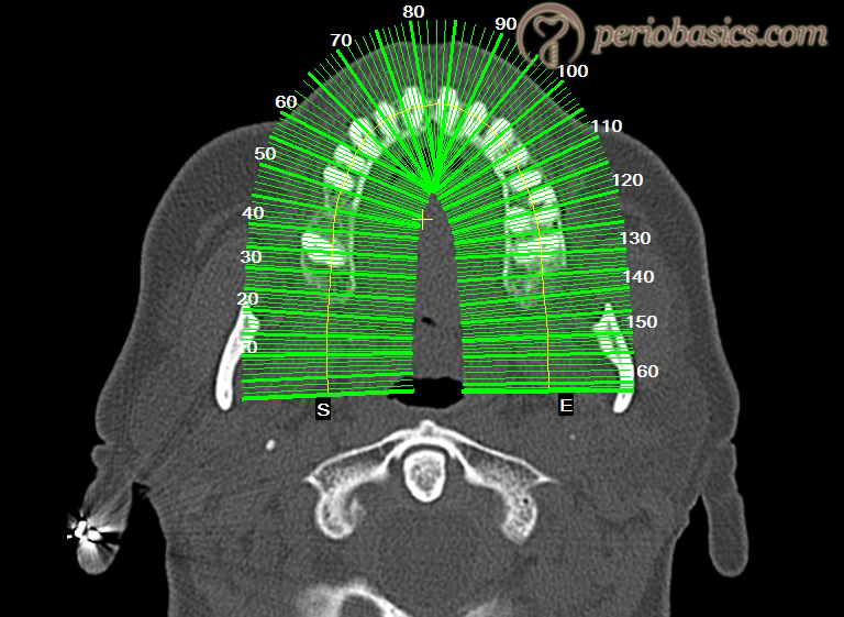
In computed tomography, a cross-sectional image is produced by scanning a transverse slice of the body from different angular positions while the tube and detector rotate 360° around the patient with the table being stationary. The image is reconstructed from the resulting projection data.
Computed tomography can be divided into 2 categories based on acquisition X-ray beam geometry; namely: fan beam and cone beam. In fan beam scanners, data is acquired using a narrow fan-shaped X-ray beam transmitted through the patient. The tomographic image is derived in two steps. In the first step, the physical measurement of attenuation of X-rays traversing the patient in different directions is measured. Secondly, mathematical calculation of the linear coefficients, μ is done all over the slice. The interpretation of the images obtained slice by slice usually in the axial plane is done by stacking the slices to obtain multiple 2D representations.
Cone-beam machines emit an X-ray beam shaped like a cone rather than a fan as in conventional CT machines. After this beam passes through the patient, the remnant beam is captured on an amorphous silicon flat panel or image intensifier/charge-coupled device (CCD) detector. The beam diameter ranges from 4 to 30 cm and exposes the head in one pass around the patient capturing from 160 to 599 basis images. In this way, 3-D images of bone or soft tissue surfaces can be generated.
Sequential CT:
Here, the patient remains stationary during the scan and the X-ray projector tube and detector move 360° around the patient. The scan volume is covered by subsequent axial scans in a “step-and-shoot” technique. In between the individual axial scans, the table is moved to the next z-position. The number of images acquired during an axial scan corresponds to the number of active detector slices. For example, a scan with 4×1 mm collimation provides either four images with 1-mm section width, two images with 2-mm section width, or one image with 4-mm section.
Spiral CT:
It is also known as “volume scanning“. Since its clinical introduction in 1991, volumetric CT scanning using spiral or helical scanners has resulted in a revolution in diagnostic imaging. In this case, unlike the sequential CT, the patient on the table is moved continuously through the scan field in the Z direction while the gantry performs multiple 360° rotations in the same direction. The X-ray thus traces a spiral around the body and produces a data volume.
The pitch is an important parameter to characterize a spiral/helical scan. According to (Inter-national Electro-technical Commission 2002) IEC specifications,
p = table feed per rotation/total width of the collimated beam
For general radiographic applications, clinically useful pitch values range from 0.5 to 2.
Ideally, volume data obtained are of high spatial resolution and are isotropic in nature. Each image data element (voxel) is of equal dimensions in all three spatial axes, and this forms the basis for image display in arbitrarily oriented imaging planes. Each voxel contains 12 bits of data and ranges from -1000 (air) to +3000 (enamel) Hounsfield’s units.
Cone-Beam CT Technology (CBCT) or Cone Beam Volumetric Tomography (CBVT):
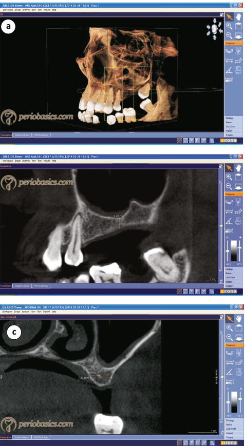
Cone Beam CT/VT refers to a tomographic imaging beam that is concentrated in a narrow field of the body. Multi-dimensional images of the hard tissue of the jaws can be obtained using this technology. Cone beam CT provides an image of hard tissue that has no distortion and is anatomically correct. Cross-sectional axial, coronal, sagittal, cephalo-metric, or panoramic views can be obtained using CBCT.
CBCT scanners are based on volumetric tomography, using a 2D extended digital array, providing an area detector. This is combined with a 3D X-ray beam. It involves a ……….Contents available in the book……….Contents available in the book……….Contents available in the book……….Contents available in the book……..
The main advantage of CBCT in the diagnosis of an implant case is that it provides clear images of highly contrasted structures and is extremely useful for evaluating bone 4, 5. The images obtained are more accurate on CBCT as compared to conventional CT because of the high resolution of the image. The image is produced by volumetric data, the smallest unit of which is known as a voxel. Each voxel represents the degree of X-ray absorption. In conventional CT, the voxels are anisotropic (rectangular) cubes where the longest dimension of the voxel is the axial slice thickness and is determined by slice pitch, a function of gantry motion. In CBCT these voxels are isotropic i.e. equal in all 3 dimensions.
Another advantage is the reduction of X-ray dosage due to collimation of the primary x-ray beam to the area of interest. It has been shown that the effective dose of radiation in CBCT is significantly reduced by up to 98% (average range 36.9-50.3 microsievert [μSv]) 6-10 as compared to “conventional” fan-beam CT systems (average range for mandible 1,320-3,324 μSv; average range for maxilla 1,031-1,420 μSv) 11-13.
One more advantage of CBCT is the reduction in the image artifacts. Two main reasons for this artifact reduction are manufacturers’ artifact suppression algorithms and increased number of projections. At present CBCT technology is widely used in implant dentistry.
Magnetic resonance imaging
Magnetic Resonance Imaging (MRI) is a widely used diagnostic tool in the medical field. This technique was first introduced by Lauterbur in 1972. The phenomenon of magnetic resonance results from the dynamics of molecular spins in combined static and oscillating magnetic fields. The pioneer work in this field started way back when Rabi first showed that an oscillating magnetic field could induce transitions between levels associated with the spin state of various nuclei in an applied static magnetic field 14. To understand the mechanism of functioning of an MRI scan let us first understand the basics of magnetic resonance first. Take an example of the compass. If it is placed near a magnet, the needle of the compass aligns itself in the magnetic field. Compass needle slowly moves as its motion is slowed by adding a liquid medium in the compass. If it is not there, the needle oscillates ……….Contents available in the book……….Contents available in the book……….Contents available in the book……….Contents available in the book……..
If a compass is placed in a strong magnetic field, the needle of compass soon aligns itself in the magnetic field. Now, if we place a small magnet near the needle aligned in a strong magnetic field, it moves as it is given a small push perpendicular to the magnetic field. It shall vibrate and soon come to its original position. The oscillations produced by doing this are referred to as resonance frequency. The radio waves produced because of this oscillation can be recorded.
These magnetic needles in our body are the nuclei of the hydrogen molecules, components of water molecules present abundantly in our body. In MRI scan the weak push to these molecules is given by placing magnets in a perpendicular direction and moving them towards and away from these nuclei. The radio waves emitted are recorded and the data is interpreted to make a three-dimensional image of the region under investigation.
Advantages:
The main advantage of the MRI scan is its ability to demonstrate the soft tissue. Studies have been done on the ability of this technology to locate the inferior alveolar canal 15. In cases where the bone density is low, the primary diagnostic techniques like CT-scan/CBCT fail to clearly differentiate the inferior alveolar canal. MRI-scan is used in such cases to locate the same. The inferior alveolar canal appears as a black void within the high-signal cancellous bone. Peri-implant tissue can be visualized better with the help of MRI-scan than other imaging techniques.
Conclusion
The above-explained diagnostic imaging techniques are routinely used in implant dentistry. Many advances have been made in radiographic diagnosis with the help of computers which have provided us interactive softwares. The implant position and angulation can be simulated in the maxilla or mandible before actually placing them in the patient. Computer-guided implant placement is becoming popular because by using this technology the surgical errors can be avoided.
References
References are available in the hard-copy of the website.
Periobasics: A Textbook of Periodontics and Implantology
The book is usually delivered within one week anywhere in India and within three weeks anywhere throughout the world.